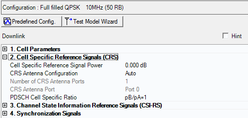
One cell specific reference signal is transmitted from each downlink antenna port.
The downlink cell specific reference signal can be used for the following purposes:
Cell search and initial acquisition
Downlink channel quality measurements
Downlink channel estimation for coherent demodulation/detection at the UE
Additional Downlink parameters are described in Cell Parameters (Basic LTE-A FDD Downlink), Synchronization Signals (Basic LTE-A FDD Downlink), and Channel State Information Reference Signal Parameters (Basic LTE-A FDD Downlink).

|
1. Cell Parameters |
|---|
Range: -60.000 to 20.000 dB
Default: 0.000 dB
Enter a power level in dB for the cell specific reference signal.
Choice: Auto | Manual
Default: Auto
Double-click or use the drop-down menu to select the CRS Antenna Configuration.
This parameter specifies both the Number of CRS Antenna Ports and the CRS Antenna Port settings. The possible settings are either Auto (automatically set by the software) or Manual (you can set them).
Choice: 1 | 2 | 4
Default: 1
Double-click or use the drop-down menu to select the number of antenna ports for the cell specific reference signals (CRS). The combination of the number of CRS antenna ports setting and the total number of antennas determines the resource elements that are reserved for reference signals as described in 3GPP TS36.211.
If CRS Antenna Configuration is set to Auto, the software sets the number of CRS Antenna Ports equal to or less than the Total Number of Antennas.
Examples (where: CRS Antenna Configuration = Auto):
Total Number of Antennas = 4, then the Number of CRS Antenna Ports = 4
Total Number of Antennas = 8, then the Number of CRS Antenna Ports = 4
The Number of CRS Antenna Ports should always be equal to or less than the Total Number of Antennas.
Choice: Port 0 | Port 1 | Port 2 | Port 3
Default: Port 0
Double-click or use the drop-down menu to select the virtual antenna port used for CRS transmission. Available port selections depend on the Number of CRS Antenna Ports selected.
If CRS Antenna Configuration is set to Auto, CRS Antenna Port is set same as ((Antenna Port) mod (Number of CRS Antenna Ports)).
|
Total Number of Antennas |
Antenna Port |
Number of CRS Antenna Ports |
CSI-RS Antenna Configuration |
CRS Antenna Port |
|---|---|---|---|---|
|
1 Antenna |
Port 0 |
1 |
Manual |
Port 0 |
|
2 Antennas |
Port 0, 1 |
1 |
Manual |
Port 0 |
|
|
|
2 |
Manual |
Port 0, 1 |
|
4 Antennas |
Port 0, 1, 2, 3 |
1 |
Manual |
Port 0 |
|
|
|
2 |
Manual |
Port 0,1 |
|
|
|
4 |
Manual |
Port 0, 1, 2, 3 |
|
|
|
|
Auto |
Same as: (Antenna Port) mod (Number of CRS Antenna Ports) |
Refer to 3GPP TS 36.211.
Choice: pB/pA=1 | P_B=0 | P_B=1 | P_B=2 | P_B=3
Default: pB/pA=1
Double-click or use the drop-down menu to select the PDSCH cell specific ratio.